Replacing a Honeywell VisionPRO IAQ (TH9421C1004 + EIM) with an ecobee Smart Thermostat Enhanced
Trigger Warning: I used AI extensively throughout this process, including writing this article. If this bothers you, stop reading now.
tl;dr: I asked ChatGPT how I could replace my proprietary Honeywell IAQ thermostat with an ecobee. It asked for some photos and took me through the whole process from start to finish. It was amazing.
This article is still a work-in-progress, so check back for updates.
The Honeywell VisionPRO IAQ can make an ordinary furnace and air conditioner look incompatible with a modern smart thermostat. Remove it from the wall and you see only three terminals—1, 2, and 3—instead of R, C, W, G, and Y.
Those functions have been moved to a proprietary Honeywell Equipment Interface Module (EIM), normally installed near the furnace. Mine operates a conventional single-stage gas furnace and air conditioner. After verifying that the EIM controlled nothing else, I removed it and connected an ecobee Smart Thermostat Enhanced to the furnace’s standard 24-volt controls.
This guide documents that specific conversion, including the checks that made removing the EIM appropriate. Nobody had this process well documented on the Internet, so I suppose it was my job.
Scope: This is a record of one installation, not a universal wiring prescription. My system has no heat pump, zoning, humidifier, dehumidifier, ventilator, or second heating/cooling stage. If your equipment differs, your wiring and ecobee configuration will also differ.
Safety: HVAC thermostat wiring is nominally low voltage, but an accidental short can damage the furnace control board or blow its low-voltage fuse. Turn off power before opening equipment or moving wires. If you cannot positively identify every connected terminal and cable, stop and call an HVAC professional.
The system I started with
My original system consisted of:
- Honeywell TH9421C1004 VisionPRO IAQ thermostat
- Honeywell THM5421C Equipment Interface Module
- Conventional single-stage gas furnace
- Conventional single-stage air conditioner
- Furnace control-board terminals
R,C,W,G, andY - No heat pump or auxiliary heat
- No zoning
- No humidifier, dehumidifier, ERV, or HRV
The EIM had three cable bundles:
- A thermostat cable connected to EIM terminals
1,2, and3 - A furnace cable using
R,C,W,G, andY - An outdoor-condenser cable using
YandC
The EIM’s R and Rc terminals were jumpered. Rh, W2, Y2, AUX1, AUX2, L, OUT, IN, and DATS were unused.
The annotated photo below was taken during the initial survey. The condenser label was still tentative at that point; I verified the cable by tracing its two conductors to the furnace-board Y and C circuit before changing any wiring. Ignore that “probable part”, this was my condenser cable and I didn’t get around to updating this image.
Photo of the old Honeywell Thermostat:
Photo of the old Honeywell Thermostat wiring:
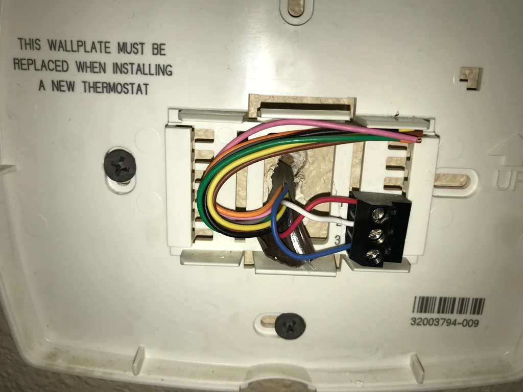
Photo of the EIM board before modification:
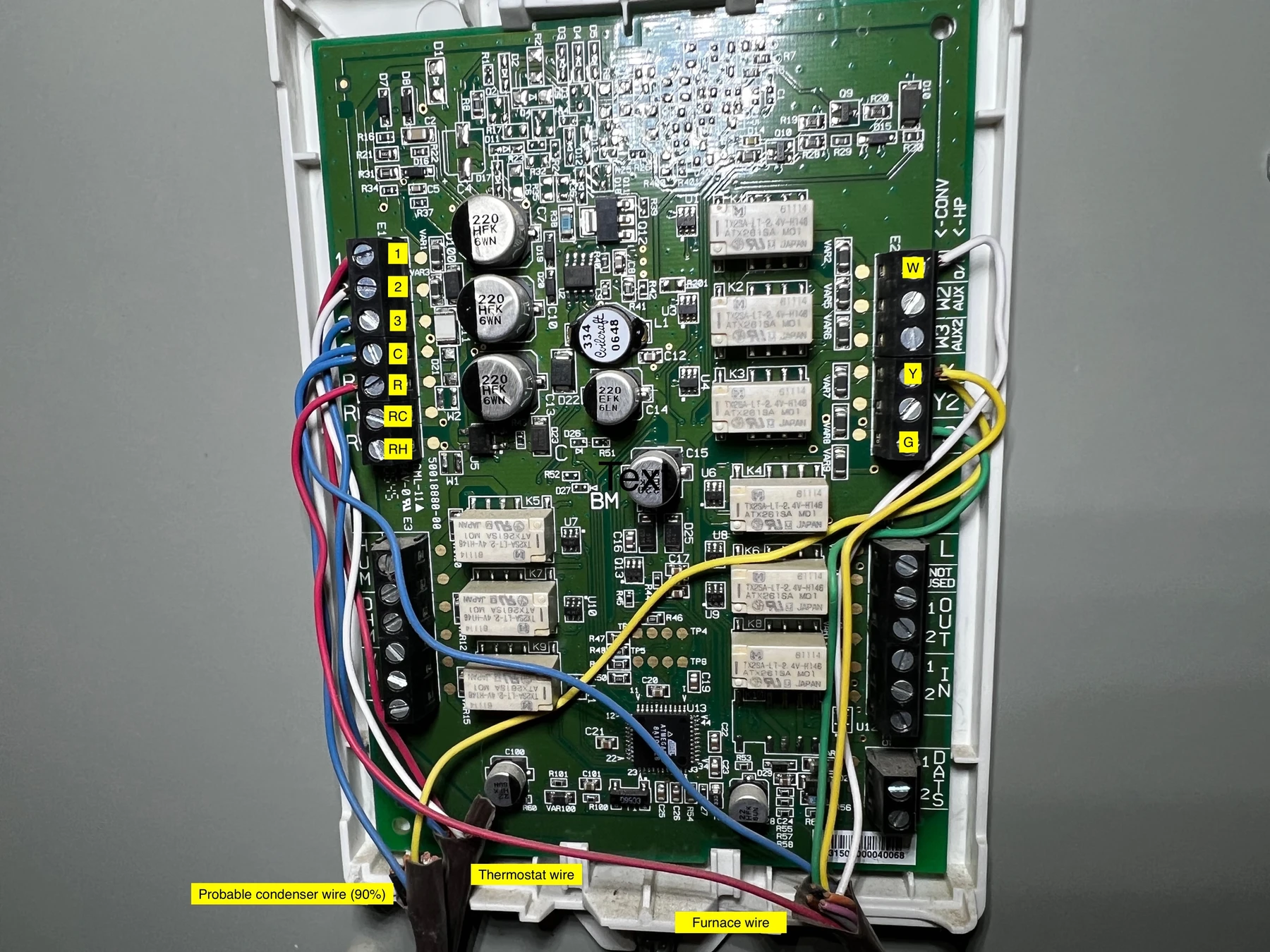
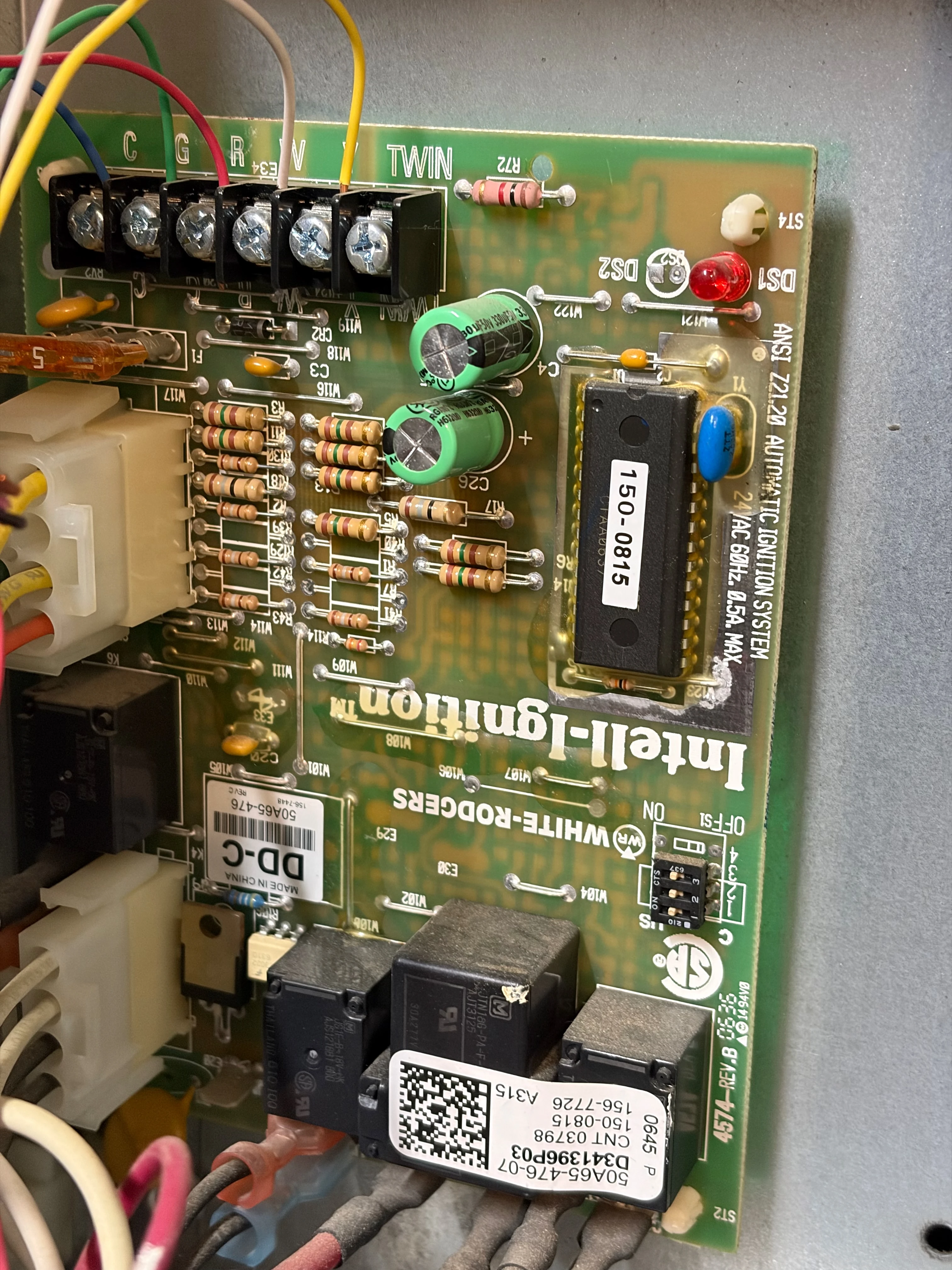
Photo of the furnace control board before modification:
Why Honeywell uses an EIM
The TH9421C1004 is a communicating thermostat. Its three numbered conductors carry power and digital communication between the wall unit and the EIM. They are not three conventional calls for heat, cooling, and fan.
The EIM receives thermostat commands and operates relays connected to the HVAC equipment and supported accessories. This let Honeywell support many functions with only three conductors to the living space.
BEFORE

  TH9421C thermostat        Honeywell EIM          Conventional equipment
  +----------------+       +--------------+       +---------------------+
  | terminals 1/2/3|======>| communication|------>| R C W G Y           |
  +----------------+       | and relays   |------>| condenser Y and C   |
                           +--------------+       +---------------------+
An ecobee does not speak the TH9421C/EIM communication protocol. It expects individual conventional conductors. Therefore, the old thermostat wires cannot simply be moved from Honeywell terminals 1, 2, and 3 to three arbitrarily chosen ecobee terminals.
Can your EIM be removed?
Remove an EIM only when every function it performs can be reproduced by the new thermostat and wiring. Record every occupied EIM terminal—not merely those at the wall thermostat.
This conversion was straightforward because the EIM’s equipment side exposed only the five standard functions used by a one-heat/one-cool conventional system:
| Terminal | Function in this system |
|---|---|
R | 24 VAC power from the furnace transformer |
C | Transformer common and condenser return |
W | First-stage heat call |
G | Indoor blower call |
Y | First-stage cooling/compressor call |
Do not use this wiring plan without further design work if you find any of the following:
- A heat pump,
O/Breversing-valve connection, or auxiliary/emergency heat W2,W3,Y2, or other active stages- A zone panel or motorized dampers
- A humidifier, dehumidifier, ERV, HRV, or other accessory connected to the EIM
- Outdoor, return-air, discharge-air, or remote indoor sensors that affect system operation
- Dual-fuel logic, ventilation interlocks, or equipment-protection controls
- Proprietary or communicating HVAC equipment instead of conventional 24 VAC inputs
- Any occupied terminal or conductor whose purpose you cannot verify
Unused features do not need to be reproduced; occupied terminals do. Another THM5421C installation may not match mine.
Plan the wiring path before disconnecting anything
This installation needs five wires: R, C, W1, G, and Y1. Although the Honeywell used only three, its cable may contain unused wires folded into the wall.
I found enough usable existing wires, so I did not install new cable. I assigned them by function and labeled both ends; insulation colors were only identifiers.
If fewer than five usable wires reach the thermostat, new 18/8 cable is the cleanest long-term solution and leaves spares. The ecobee Power Extender Kit fits certain systems without C, but was unnecessary here.
If wires must be extended at the former EIM location, use connectors listed for the wiring material and gauge. Keep splices protected, supported, and accessible inside an appropriate equipment enclosure, and follow the furnace manufacturer’s instructions and local electrical requirements. Do not rely on twisted wires and tape.
Photo of old thermostat removed from the wall, showing terminals 1/2/3 and all previously unused conductors pulled forward:
Tools and materials
- ecobee Smart Thermostat Enhanced and backplate
- Small flat-blade and Phillips screwdrivers
- Wire labels and a permanent marker
- Phone or camera for before-and-after photos
- Wire stripper suitable for 18 AWG thermostat wire
- Multimeter, if you know how to use it safely
- Listed lever connectors (Wago 221) or insulated butt splices to connect wires securely
- 18/8 thermostat cable if the existing cable lacks enough wires or length
The ecobee trim plate, wall anchors, and drill may also be useful depending on the wall opening left by the Honeywell thermostat.
Wire-by-wire migration
The safest mental model is to ignore wire color and follow each electrical function from the furnace board to its new ecobee terminal.
| Function | Original path through the EIM | Final path after EIM removal |
|---|---|---|
| 24 VAC power | Furnace R → EIM R; EIM R/Rc jumpered | Furnace R → ecobee R |
| Common | Furnace C → EIM C | Furnace C → ecobee C |
| Heat | Furnace W → EIM W | Furnace W → ecobee W1 |
| Blower | Furnace G → EIM G | Furnace G → ecobee G |
| Cooling | Furnace Y → EIM Y | Furnace Y → ecobee Y1 |
| Condenser | Condenser Y/C joined through the equipment wiring | Condenser Y remains with furnace Y; condenser C remains with furnace C |
| Honeywell data bus | Thermostat 1/2/3 → EIM 1/2/3 | Removed; there is no ecobee equivalent |
The condenser conductors do not run to the ecobee. Its Y shares furnace Y, and its C shares furnace common. An ecobee cooling call energizes that circuit through the furnace wiring.
AFTER

                    ecobee Smart Thermostat Enhanced
                  +-----------------------------------+
                  |  R      C      W1      G      Y1  |
                  +--|------|------|-------|------|---+
                     |      |      |       |      |
                     |      |      |       |      |
  Furnace board      R      C      W       G      Y
                  +--|------|------|-------|------|---+
                  |  |      |                     |   |
                  |  |      + heat                |   |
                  |  + common                     |   |
                  |  24 VAC                       |   |
                  +-------------------------------+---+
                            |                     |
                            C                     Y
                            +--- outdoor condenser+
Installation procedure
1. Shut down and document the system
Set the thermostat to Off, then turn off power to the furnace at its service switch or breaker. Turn off the outdoor A/C disconnect or breaker as well if you will be handling its control conductors. Confirm that the old thermostat and EIM are no longer powered.
Some furnaces have a door interlock that cuts power when the access panel is open; remember this when testing.
Photograph the furnace board, EIM terminals, cable jackets, and wall thermostat. Label each cable by destination and each conductor by its current terminal. Keep disconnected conductors separated: shorting R to C can open the control-board fuse.
2. Verify the system type
Trace EIM R, C, W, G, and Y to the furnace board. Confirm that the outdoor cable lands on Y and C, and that all other EIM equipment/accessory terminals are unused.
Stop if the physical wiring differs from the plan. Old installer settings are useful evidence, but actual connections and equipment documentation are authoritative.
3. Assign and label the thermostat conductors
Choose five continuous conductors and label both ends R, C, W, G, and Y. Verify uncertain continuity rather than trusting color.
The following photo shows my work in progress while the cable bundles and extensions were labeled. It is an intermediate state, not an example of finished wire dressing.
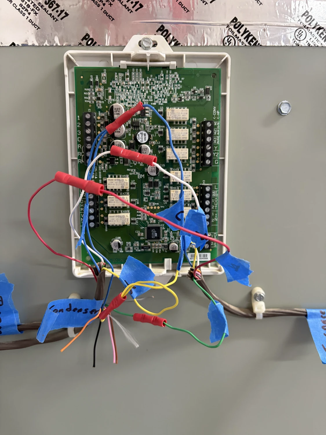
4. Remove the EIM from the control path
Disconnect the identified furnace, condenser, and thermostat conductors from the EIM. Join or route each function according to the migration table. Preserve the condenser connections to furnace Y and C.
The retired 1/2/3 assignments have no ecobee meaning. Relabel the selected conductors by their new functions.
5. Mount and wire the ecobee
At the wall, feed the labeled conductors through the ecobee backplate and mount it level. Connect:
| ecobee terminal | Connects to |
|---|---|
R | Furnace R |
C | Furnace C |
W1 | Furnace W |
G | Furnace G |
Y1 | Furnace Y |
Insert each conductor securely and tug it gently. No PEK is used in this five-wire arrangement. Attach the thermostat and reinstall the furnace panel.
Photo needed: ecobee backplate with
R/C/W1/G/Y1connected and labels visible, before the display is attached.
ecobee configuration
Restore power; startup can take several minutes. Follow the guided setup and verify that detected wiring matches the backplate.
For this system, the important equipment choices are:
- Equipment type: Conventional furnace and air conditioner
- Heat source: Gas
- Heating stages: One
- Cooling stages: One
- Heat-pump/reversing valve: None
- Accessories: None
- Fan control in heat mode: HVAC equipment/furnace
The furnace should control the blower for gas heat so it can honor warm-up and cool-down delays. The ecobee still uses G for independent fan operation and cooling airflow.
Firmware can change screen wording and order. Treat these as configuration targets and confirm them in the equipment summary.
Commissioning tests
Test one function at a time. Give the system several minutes between mode changes; thermostats and condensers commonly enforce anti-short-cycle delays.
- Thermostat power: Confirm that the ecobee remains powered and connected to Wi-Fi.
- Fan only: Set the fan to On. The indoor blower should start without the burner or condenser.
- Heat: Select Heat and raise the set point. The furnace should begin its normal ignition sequence, then start the blower after its normal delay.
- Cooling: Return the thermostat to Off long enough for any delay to expire, then select Cool and lower the set point. The outdoor condenser and indoor blower should run.
- Shutdown: End each call and confirm that the equipment stops normally. The furnace blower may run briefly after a heating call.
Home Assistant integration
There are two useful approaches. Choose one as the thermostat’s primary Home Assistant connection rather than pairing both without a specific reason.
Native ecobee integration
The native integration exposes the thermostat, sensors, comfort settings, equipment state, vacations, and several ecobee-specific actions. It is classified as Cloud Polling, so it depends on ecobee’s service and your Internet connection.
In Home Assistant 2026.3 and later, go to Settings → Devices & services → Add Integration → ecobee and follow the sign-in flow. A new developer API key is no longer required. Existing API-key installations remain supported.
HomeKit Device alternative
Home Assistant’s HomeKit Device integration communicates locally and provides push updates. The thermostat must be on the same network and available for HomeKit pairing; a HomeKit accessory can normally be paired to only one controller at a time. You do not need Apple hardware or an Apple online account merely to use HomeKit Device.
HomeKit may expose fewer ecobee-specific features, but can operate without the ecobee cloud. HomeKit Device brings ecobee into Home Assistant; HomeKit Bridge publishes Home Assistant entities to Apple Home.
Troubleshooting
The ecobee does not power on
- Confirm that furnace power is on and the furnace door is fully seated against its interlock.
- Tug the ecobee
RandCconductors and inspect their furnace-end connections. - Check the furnace board’s low-voltage blade fuse. A blown fuse often indicates that
RtouchedCwhile power was on; find the short before replacing it. - Verify approximately 24 VAC between
RandConly if you are trained to make energized measurements safely.
The fan works, but heat does not
- Confirm furnace
Wreaches ecobeeW1, notW2/OB. - Verify that the ecobee is configured for conventional gas heat.
- Watch the furnace’s normal ignition sequence and diagnostic LED. A furnace lockout or safety fault is not a thermostat-wiring problem.
Heat works, but the blower starts at the wrong time
Set fan control during heating to the HVAC equipment/furnace. That lets the gas furnace manage its warm-up and cool-down delays.
The indoor blower runs, but the condenser does not
- Confirm ecobee
Y1reaches furnaceY. - Confirm the outdoor condenser’s two control conductors remain on furnace
YandC. - Allow for the compressor protection delay.
- Check the outdoor disconnect and breaker. Do not open the condenser’s high-voltage compartment unless qualified.
Cooling works, but the indoor blower does not
Confirm ecobee G reaches furnace G and that the ecobee detected the conductor. Cooling normally requires both the Y1 compressor call and G blower call in this conventional arrangement.
Home Assistant cannot discover the thermostat through HomeKit
Make sure the thermostat and Home Assistant are on the same local network and that mDNS traffic is not blocked between them. If the ecobee is already paired to Apple Home, it may need to be removed from that Home before Home Assistant can claim the HomeKit pairing. Do not factory-reset it unless the relevant documentation specifically calls for that step.
Frequently asked questions
Can I connect Honeywell terminals 1, 2, and 3 directly to an ecobee?
No. They form the Honeywell communication link to the EIM and do not correspond to ecobee R, C, or any other three terminals. The ecobee needs individually identified conventional functions.
Do I need the ecobee PEK?
Not if five usable conductors reach the thermostat for R, C, W1, G, and Y1, as they did here. If you lack a C conductor, use ecobee’s compatibility guidance to determine whether the PEK fits your system.
Must I replace the three-wire thermostat cable?
Inspect the entire cable first. A cable may contain five or more conductors even though Honeywell used only three. If it truly contains only three, you will need a compatible alternative such as new cable or a properly designed PEK installation.
Can I leave the EIM installed?
It can remain physically mounted and disconnected, but the ecobee cannot use it as a conventional terminal adapter. Label abandoned wiring clearly. Removing unused equipment can make future service less confusing.
Does wire color determine the terminal?
No. Colors are conventions, not proof. Label by the terminal and verified destination at both ends.
Why does the condenser connect to both Y and C?
Its contactor coil needs a complete 24 VAC circuit. A cooling call supplies the switched side through Y; C supplies the return path.
When should I hire a professional?
Call a professional for active accessories, zoning, heat pumps, dual fuel, multiple stages, untraceable conductors, repeated blown fuses, or any mismatch with this example.
Result
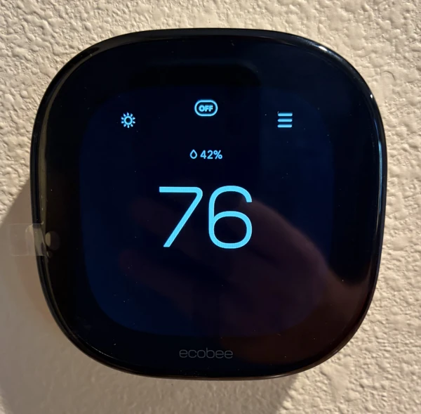
Removing the EIM exposed the conventional controls behind Honeywell’s communication layer. The finished installation uses R, C, W1, G, and Y1, with no PEK or new thermostat cable.
The real work was not moving wires. It was proving what every wire did, confirming which EIM capabilities were unused, and testing each function after the conversion. That documentation is what makes the result serviceable rather than merely functional.